NAVIONICS TEAM
Coined by a past electrical lead, “navionics” is a merging of “electronics” and “naval” not unlike how avionics refers to aircraft instruments. Navionics members focus on the designing, building, and testing of the electrical system of our robots. Members are accepted regardless of experience with circuits or electronics and are aided with lessons and one-on-one pairing. The team’s goal is to ensure that all members have the opportunity for hands-on experiences and learning that is often lacking in the traditional classroom.
About the Subteam
The Navionics Subteam designs, builds, and tests all of the custom electronics in our Autonomous Underwater Vehicle (AUV). Due to the tight space constraints, we custom build the majority of our electronics to ensure they best fit the needs of the vehicle in the smallest possible size. We design our own custom Printed Circuit Boards (PCBs) in Altium Designer, an industry standard PCB design tool. The Navionics team is additionally responsible for assembling and testing our circuit boards, giving members skills in advanced SMD soldering and design validation. We strive to ensure that each member gets the opportunity to take on a project that they find the most interesting, and get real world engineering experience.
This year Navionics has continued work on improving the Mark 2 electronics system in Talos. Additionally, a whole new AUV has been designed and is ready to make a splash in competition. Read more about these projects below and see examples of what our Subteam works on.

Talos Mark 2 Electronics
The Mark 2 electronics is the second generation electronics system designed for our vehicle, Talos. We took the lessons learned from our previous Mark 1 electronics used in our previous vehicle Tempest, to make a more stable and reliable electronics system. Mark 2 marked a lot of firsts for the Navionics team, including switching to a distributed architecture, improving our fault resiliency and improving robustness of the communications on the vehicle. If you want to learn about how to design resilient systems, and be able to see your electronics designs running in our vehicle, join our Navionics Subteam. Members get firsthand experience creating and validating advanced designs to best handle the challenging task of running AUVs.
Over this past year we focused on improving the Mark 2 electronics design. This involved removing legacy circuitry used to support old Task Mechanisms. This new space allowed us to add brighter Status LEDs so that the robot’s state can be clearly seen when it is running while submerged, as well as a new IVC Board.
All of our board design files are available on our GitHub, along with the exported PDF Schematics.

Mark 2 System Architecture
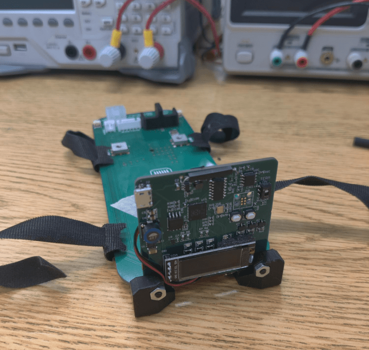
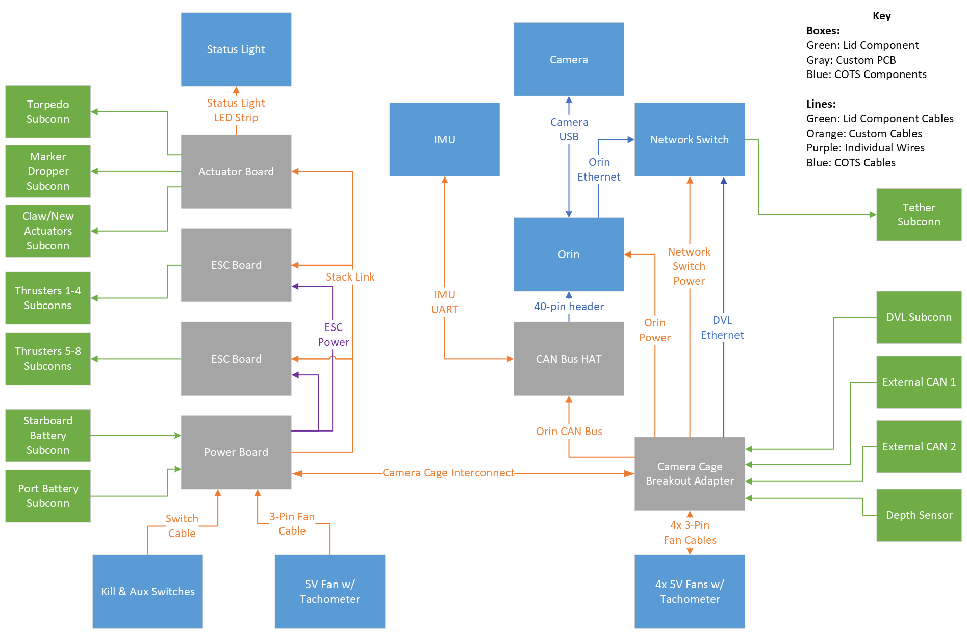
The Mark 2 Architecture consists of 6 custom designed boards, all handling a separate responsibility of the vehicle. The port side of the vehicle contains the four primary circuit boards, known as the Board Stack (see the picture above). The starboard side of the vehicle contains the computational and sensor elements of the vehicle, with the NVIDIA Jetson Orin at the heart. Additionally we use a StereoLabs Zed 2i for 3D vision, and a VectorNav VN-100 IMU for sensing orientation and acceleration. We use CAN Bus as the primary communication link between the main computer and the rest of the electronics system. This is the only data protocol traveling between systems in the vehicle, improving the ease and reliability of communication between systems.
Mark 2 Combined Power/Actuator Board
The Mark 2 Combined Power/Actuator Board combines the responsibilities of the Mark 2 Power and Actuator boards. This board was developed this past year to shrink the existing system, allowing the space to be used for more systems. It has two TDK-Lambda Voltage Regulators, capable of providing up to 250W of power. It additionally contains the Kill Switch circuitry to cut off power to the thrusters, ensuring the AUV is in a safe state when the kill switch is removed. It also contains several sensors to provide telemetry on the current state of the electronics system, such as reading the voltage of the various voltage rails as well as board stack temperature.
The RoboSub competition has several tasks that our vehicle must be able to perform, such as picking up objects with a claw, dropping markers, or firing torpedoes through a target. These competition task mechanisms require additional control and circuitry that is not part of other systems on the vehicle. The Actuator Board contains all of the necessary components to drive these task mechanisms to allow the robot to perform the required tasks for competition. This board has the required circuitry to drive these task mechanisms (described in more detail on the Mechanical Team Page).
View Schematic


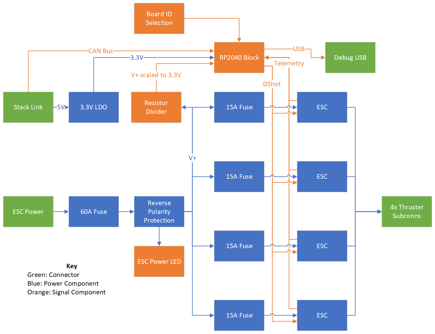
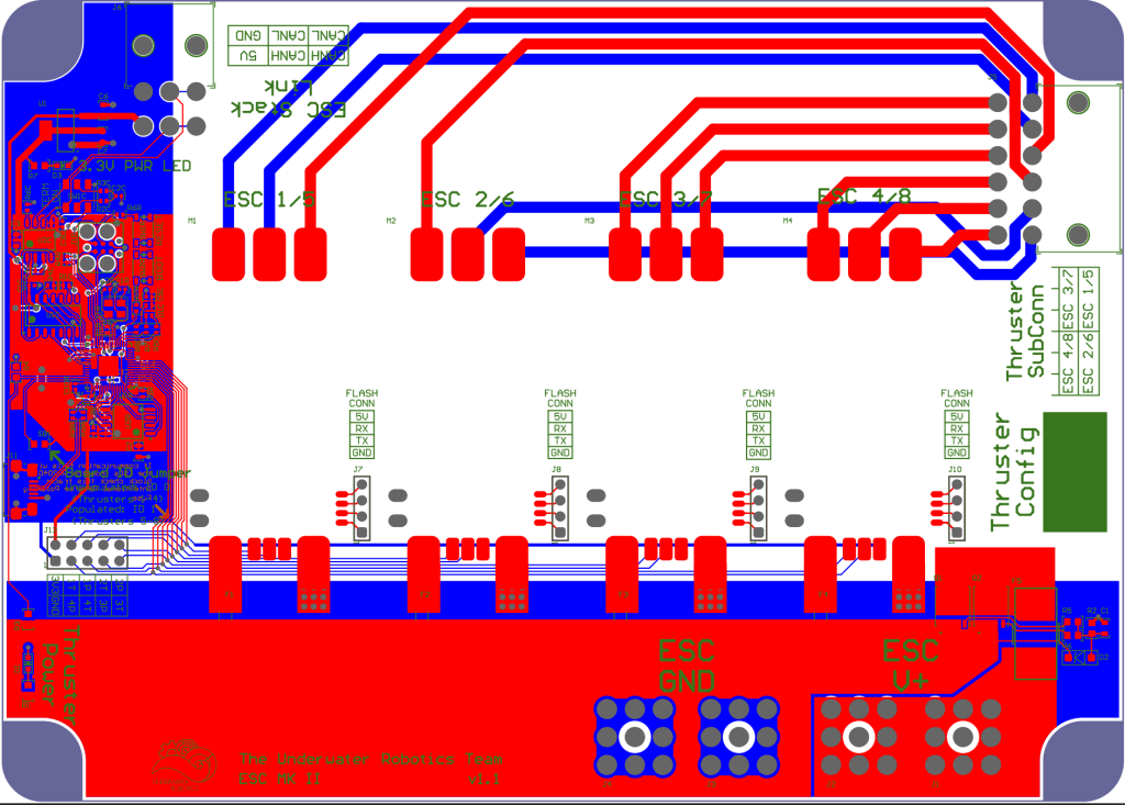
Mark 2 ESC Board
The Mark 2 Electronics contains 2 ESC boards, each containing 4 Electronic Speed Controllers (ESCs) which are required to control the vehicle’s thrusters. We use 8 APD 80F3 speed controllers on our vehicle, using the DShot digital protocol to send commands. Switching to DShot not only increases resilience to noise, but also provides telemetry back from each of the ESCs to ensure that each thruster is operating as expected.
View Schematic
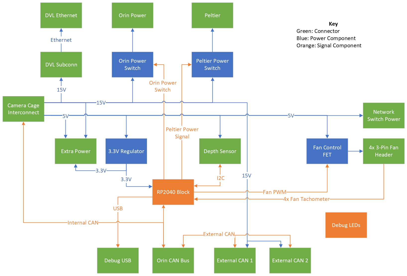
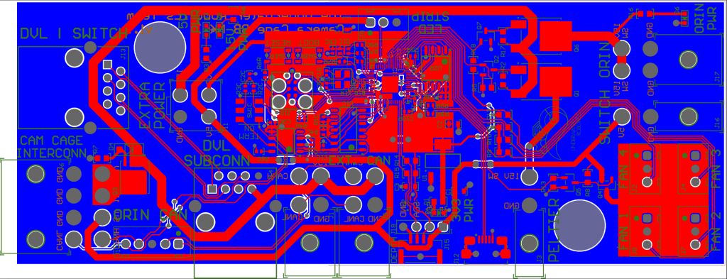
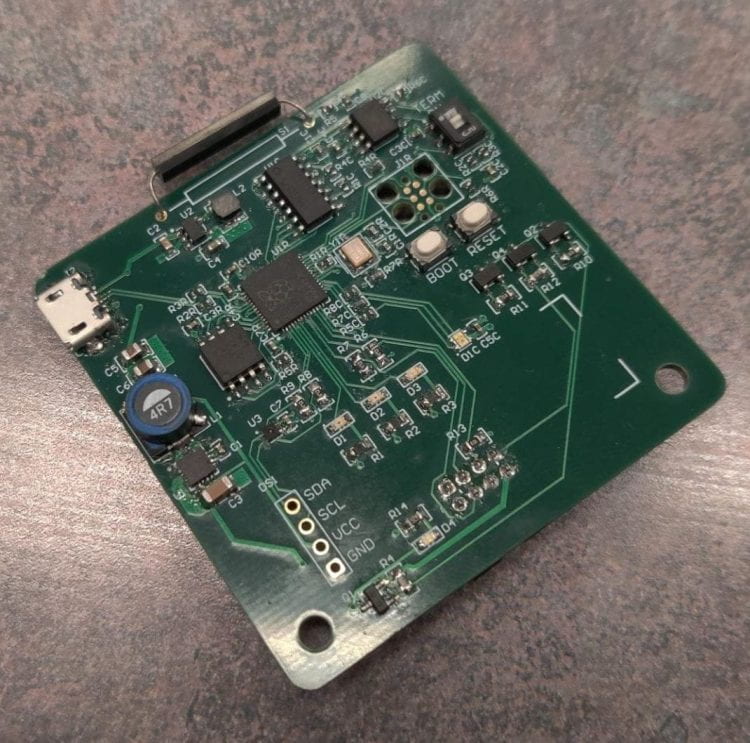
Mark 2 Camera Cage Breakout Board
The Camera Cage contains several off the shelf components, each with their own power and communication requirements. To simplify the wiring in this side of the vehicle, the Camera Cage Breakout Board takes in a single harness from the Electronics Stack and breaks out connectors for each of the components on the starboard side of the vehicle. It additionally has a microcontroller to poll the Blue Robotics Depth Sensor and provide control to power cycle the computer, manage the cooling, and provide temperature information for the computer cage.
View Schematic
Mark 2 LED Status Boards
The LED Status Boards are the new top of the Mark 2 Electronics Stack. This board is a replacement to the NeoPixel RGB Light Strips used on during the previous year to show the status of the vehicle’s autonomous functions. These RGB lights would show different colors and patterns so that the team could see what the robot was currently doing while untethered during a competition run. During the 2023 RoboSub competition, the team found that these RGB light strips were not bright enough to be seen in the direct sunlight at competition. This year, the team developed a new system with over 100 Watts of LEDs. The design was split into two boards: a multilayer control board which can hold all of the integrated circuits to drive the LEDs, and a dedicated aluminum PCB which holds the high power LEDs. This aluminum board is easier to cool compared to a standard PCB, but is only 1 layer.
View the schematics for the Control Board and the Aluminum LED Board


IVC Board
With the addition of a second AUV, UWRT decided to create the IVC Board (Inter-Vehicle Communications). This board merges the abilities from the old Acoustics Board of identifying and locating pingers in the pool with the new ability for the AUV’s to communicate with each other. To accomplish communication, IVC uses a timer signal from the RP2040 to determine frequency to send through the transducer, which is a custom made fully floodable coil-driven speaker.
IVC is also responsible for other additional functions. One of the more important functions is the pinger detection capability which is possible by saving signal samples from different locations in the pool and comparing their amplitudes. Other functions include leak detection, connectors for LEDs, and a Bluetooth module to play music on the transducer.
View Schematic


S.S. Flip Barker Electronics
With the addition of a new AUV, a new electronics cage was necessary. Because S.S. Flip Barker’s purpose is to support Talos with only a few certain tasks, it was crucial to keep the cage as small as possible. However, using the knowledge gained from the Mark 2 redesign, we were able to create condensed boards with some overlapping responsibilities for the vehicle that allowed for such size constraints. While working around this size constraint was an extreme challenge, it was also an incredible learning experience for all members. It forced all members to use all the knowledge gained from Talos and apply it to a new vehicle design, which is no easy task.
One of the most important goals UWRT has is to raise up all members and give them the opportunity to apply themselves in these feats of engineering. So, if either this new cage design or the Mark 2 redesign has caught your interest, consider reaching out to our Navionics team and start your journey on becoming the best engineer you can be!

Primary Electrical System
Building from previous knowledge, the primary electrical system for S.S. Flip Barker follows Talos’s design philosophy. It employs a distributed control architecture in which each of the 4 boards runs its own RP2040 microcontroller and communicates over CAN communication protocol. This approach simplified integration with legacy circuity.
Similarly, the Talos Smart Battery System was reused. The reuse of this system allowed for the team to include key proven safety measures such as undervoltage, overvoltage, and overcurrent protection, cell balancing, and temperature monitoring. However, in order to account for voltage and amperage requirements required to run Seatbotix BTD 150 thrusters, a MaxAmps 8000mAh 5S LiPo battery was used.

PoHalf Board
PoHalf is the primary point of contact with the battery system and is responsible for regulating voltage levels across the entire AUV. Two TDK-Lambda Voltage Regulators are responsible for providing consistent 5V and 12V voltages, each capable of providing up to 250W of power. An onboard ADC is used to constantly monitor voltages rails to detect undercurrent events. The Kill Switch circuitry also allows for a consistent way to cut power to the SSFB’s thrusters and motors allowing for a greater amount of safety for drivers.
To limit the total number of boards on the SSFB, PoHalf also features many auxiliary features. Some of these features are five 12V toggle switches used for SSFB’s three solenoids and the Jetson Orin AGX, four pressure sensors for depth, regulator housing, and regulated line pressures, 12V fan, and humidity and temperature sensors.
View Schematic


H-Bridge Board
H-Bridge Board serves as the main motor driver board for the SSFB. Using TI’s DRV8243HQRXYRQ1, H-Bridge Board can drive up to five H-Bridge motors up to 12A. These are currently used to drive the SSFB’s two drivetrain motors and two thrusters. H-Bridge Board is able to use current feedback and fault monitoring to detect motor stalls and errors. H-Bridge Board is also used to drive servo motors present on the SSFB. The SSFB currently features three servo motors used in both the claw and the noodle winch.
View Schematic


Nano Hat Board
Nano Hat was designed as a slim extension of the 40-pin header on the Nvidia Jeston Nano. This board is designed to be attached directly on top of the Nano minimizing increases in the footprint of the device. This board extends the native communication interfaces of the Nano to include both RS232 communication and CAN communication. The RS232 interface is primarily used to directly communicate with VectorNav VN-100 IMU. The Nano Hat also provides a power toggle for the RS232 output allowing the Nano to power cycle the IMU in case of emergency. The Nano Hat uses the native CAN controller of the Nano and an external CAN transceiver to communicate with UWRT’s custom circuit boards.
View Schematic


IVC Board
With the addition of a second AUV, UWRT decided to create the IVC Board (Inter-Vehicle Communications). This board merges the abilities from the old Acoustics Board of identifying and locating pingers in the pool with the new ability for the AUV’s to communicate with each other. To accomplish communication, IVC uses a timer signal from the RP2040 to determine frequency to send through the transducer, which is a custom made fully floodable coil-driven speaker.
IVC is also responsible for other additional functions. One of the more important functions is the pinger detection capability which is possible by saving signal samples from different locations in the pool and comparing their amplitudes. Other functions include leak detection, connectors for LEDs, and a Bluetooth module to play music on the transducer.
View Schematic
Firmware Development
As part of the Distributed Architecture in the Mark 2 Electronics, each circuit board now has its own dedicated microcontroller to handle interfacing that board’s electronics to the rest of the vehicle. Each of these microcontrollers needs code written for it, referred to as Firmware. These are low cost computational devices optimized for interfacing to electronics. As such they have fewer resources and require special attention to ensure that the resources are being efficiently used. This code is the responsibility of the Navionics Subteam, rather than the Software Subteam, due to the tight constraints that microcontrollers face, with constant collaboration required between the board designers and firmware developers to ensure that the microcontrollers are effectively utilized. If you find that you enjoy working on both Electronics and Software and writing efficient, simple code, you might find that Firmware is the right place for you on the Underwater Robotics Team.
Our team primarily uses the RP2040 microcontroller, due to its low cost, availability during the chip shortage, and support for Micro-ROS. Lost cost was an important requirement as each Mark 2 board requires its own individual microcontroller. Micro-ROS is also an important requirement, as it enables interfacing with ROS (Robot Operating System), the set of libraries the Software team uses for managing and operating the vehicle. This reduces the time spent working on designing an effective interface between software and electrical systems, and instead allows us to quickly create new interfaces to share data between the two systems. This year as part of this firmware project, we pushed to not only write firmware for the new devices, but also improve the insight we have into the electronics system, with the goal of never needing to open the vehicle to debug an issue.
All of our firmware is open source on our GitHub. Feel free to explore if you are interested!
Smart Battery Housings
Two years ago we switched to a Smart Battery System which adds a Battery Management IC to each battery for the vehicle. This provides additional telemetry and protection for our vehicle’s MaxAmps 5S 8000 mAh LiPo Batteries. The smart battery housings use the Texas Instruments BQ40Z80 Lithium-Ion battery pack manager IC, which provides charge balancing, state of charge estimation, and battery protection features. We additionally created a display board which allows a magnet to be brought towards the battery to read the current charge level for the pack. The microcontroller connects to the rest of the vehicle with a CAN bus link, allowing for the remaining charge estimation to be viewed by the vehicle operator. This past year we additionally developed a custom charger to streamline charging with the Smart Battery Housings, giving real-time feedback as they charge.
The smart battery housings was one of our most ambitious projects to date, pushing our design, assembly, and testing capabilities further than we have gone before. If you want to be a part of this and make the next big project, reach out to us and join Navionics!
View the schematics for the Battery Management Board, the LCD Board, and the Charger Board.